
Macroscopic micrographs of large microsections
The usual procedure requires the sample plates to be broken down into small specimens with an edge length of just a few centimeters. The specimens can then be embedded, ground, polished, etched and then viewed under a microscope.
This procedure has several disadvantages. Firstly, the specimens must first be numbered on the reverse side and then usually cut out by external companies. The resulting cuts subsequently result in a gap between the individual microstructural images. On the other hand, with the latter, the orientation of the specimens and the numbering must always be taken into account in order to make a subsequent allocation possible.
The novel method is based on a high-resolution digital SLR camera (50 megapixels) with macro lens (magnification 1:1) and a traversing unit. The camera is mounted on the traversing unit and positioned in front of the large sample plate. A matlab control enables the automated procedure and photographing of the sample. The overlapping individual images are then combined to form a complete image.
The automated scanning of the sample surface prevents any confusion in the position assignment. In addition, the sample as a whole is retained and can be reused after the images, if necessary.
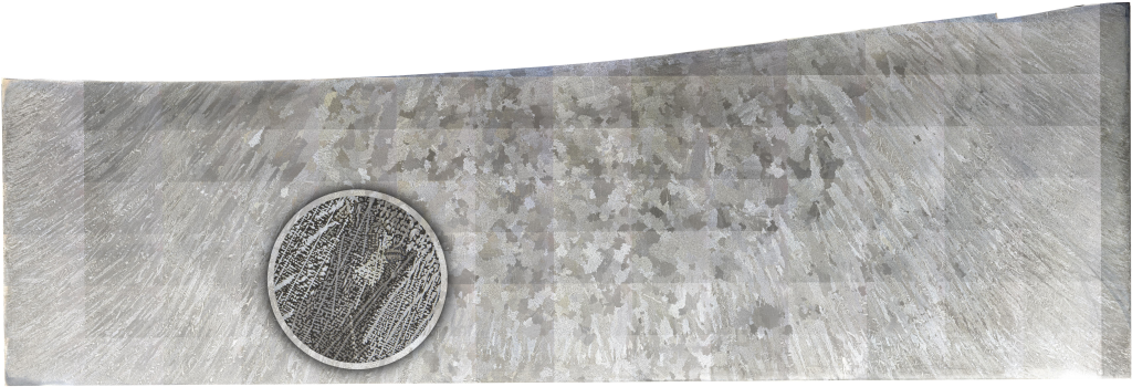
Due to the high resolution in combination with the imaging scale of 1:1, the edge length of a pixel corresponds to about 4 µm on the sample. This method can also be used to measure secondary dendrite arm distances. As can be seen in the picture, the overall image can be zoomed into the microstructure at any position.
The maximum sample dimensions for this method are currently limited to approx. 2000 mm x 2000 mm only by the traverse paths of the traversing unit.
